UVMaps and Pattern Presets - Strange Results in Daz Studio
 Diomede
Posts: 15,225
Diomede
Posts: 15,225
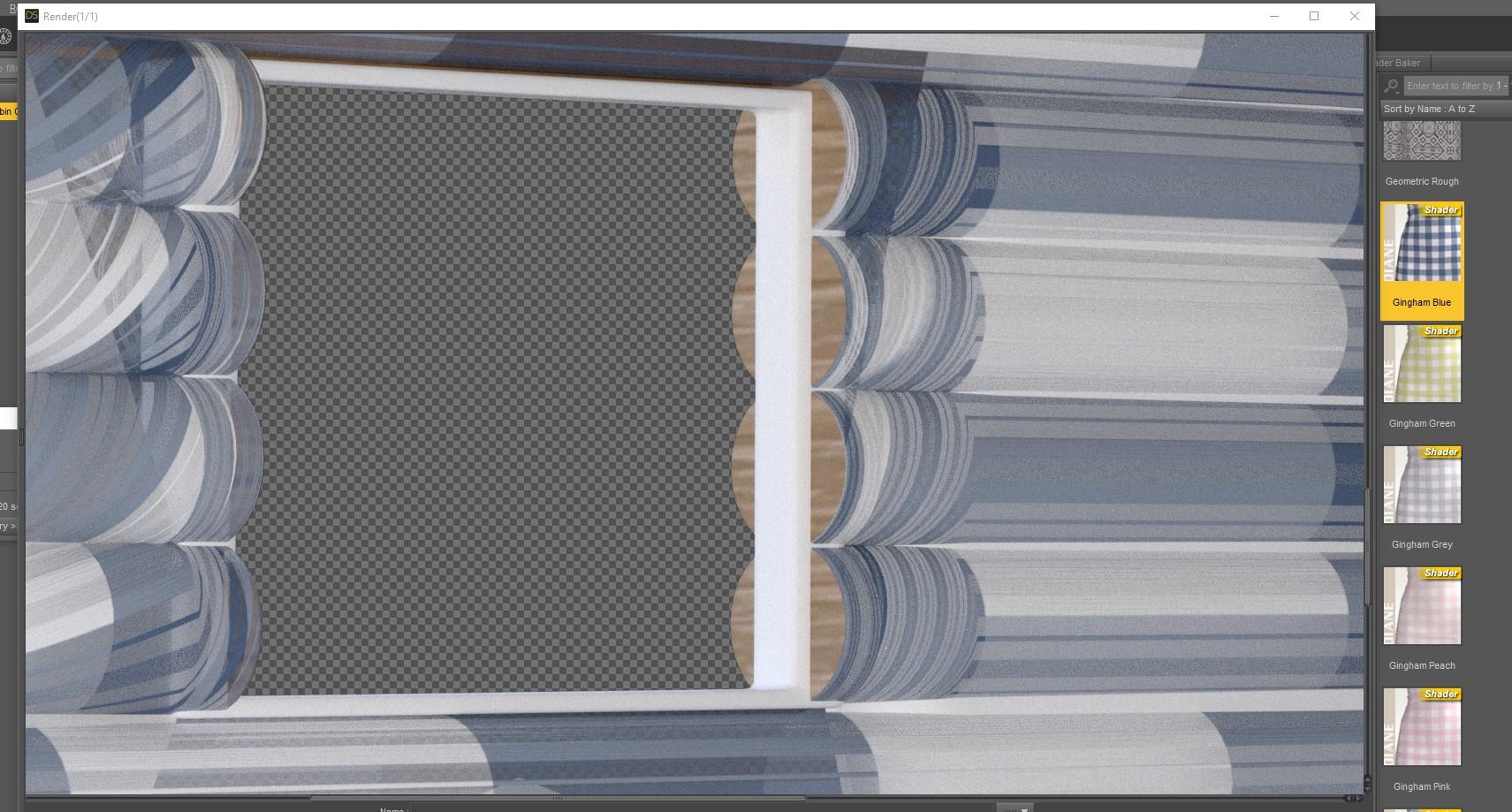
Strange results. Getting UVMap twist on side of cylinder near the cap.
I admit that I am still a beginner in many ways with Daz Studio. Surfaces and shaders are giving me strange results. I modeled a simple cabin wall made up of horizontal cylinders. The uvmaps for the sides of the logs are vertical to make it easier to apply bark shaders. I can confirm in my modeling program that the uvmaps are pretty clean, and do not twist or bend from the middle to the cylinder to closer to the end. Applying a tile map in my modeling program and test rendering confirms no distortion near the ends.
Unfortunately, when I import the model in Daz Studio and apply a preset, the shaders near the ends of the cylinders are all twisted and gnarly. I applied a stripe preset instead of bark for this post just to make it more clear that the ends of the cylnders were strange. I can't figure out why.
Probably something simple like a box to check or uncheck but I don't know what it is.
Daz 3D is part of 
Connect
DAZ Productions, Inc.
7533 S Center View Ct #4664
West Jordan, UT 84084
Licensing Agreement | Terms of Service | Privacy Policy | EULA
© 2025 Daz Productions Inc. All Rights Reserved.
Comments
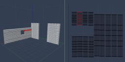
It looks to me, like the uv map in the twisted area is flipped vertically from the coordinates of the rest of of it. Isolate that area on the UV and flip it vertically and see if that helps. UV mapped cylinders are easier to deal with if all the areas along the outside are welded to each other at the vertices, making one large flat area for the curved surface and two round areas at the caps. All the edges in red in the image are welded. If yours are welded as well, I'm not sure how that twisting is occurring. It's the only thing I can think of. I don't see your end cap uvs though...are they separate or not...that could also be interfering - stretching the uv at the ends.
Laurie
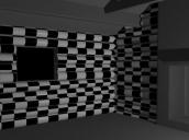
You can also map the cylinder like the attached, tho it makes it harder to texture the end caps ;).
It looks like your end caps have been mapped edge on, which means you'll have nothing but problems in that area.
Laurie
Fix - strange but worked. The strange results were only when subD was enabled. So, there was something about the model, even though I am sure that I braced the ends (see screenshot in first post). The distortion disappeared when I turned off subD. Given the simplicity of the model, I just replaced the log meshes with new cylinders with an extra brace. Problem fixed, but still strange.
@AllenArt, thank you for the replies. Excellent suggestions. In this case, my UVMap for the caps was like your first post, with the caps as circles separated from the sides. I just hid a lot of the rest of the set to make the distorted sides more obvious. Your suggestion didn't turn out to be the issue in this case, but I very much appreciate the detective help. It could have been that.
you do know you can crease edges in Carrara which is probably what you should have done on the caps
(and smoothed the sides)
You've done it. Really gone & done it.
I have been wondering how to simulate threads without the expense of modelling the threads. Doing a texture map & displacement around a cylinder and then putting it at an angle means the thread can be done with a straight & easy to draw texture map. Thanks.
Regards,
Richard.
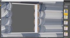
You can see in the original post that the black/white tiling test render in Carrara does not have distortion, and the Carrara uvmap for the sides is flat. Not sure what went wrong in the export/import bit but something got fouled up. I'm good for now with the substitute, but after my project I will go back and do more investigation of the original obj.