Backface culling and Inverted Hull in 3Delight and Iray
Update: the shaders in this thread were made with Daz Studio 4.15.0.30.
Update: I was able to modify the Iray face culling shader to get a proper Inverted Hull, see details in my next post.
Original post (with broken images fixed):
In the process of comparing various rendering techniques for my projects, I tried to use the classic Inverted Hull method to get an outline around my toon characters. It's pretty straightforward in 3Delight, but I couldn't quite get it to work properly in Iray.
In the future, I don't think I will be using Iray for NPR (Non-Photorealistic Rendering). Nonetheless, having benefited from others posting about their experiences, I decided to do the same and describe what I tried to do and why, and how it turned out.
The conclusion will be that it is possible to do backface culling in Iray, but there are limitations making the technique inconvenient for Inverted Hull.
A) Inverted Hull in 3Delight
The idea is to add a geoshell to a model and make it so that the faces of the geoshell facing toward the camera are invisible, while the faces facing away are visible. Because most of this backward-facing geoshell is hidden by the model, the end result is a colored outline that fits the model.
The following picture is a comparison of various versions of a 3Delight render: no outline, Daz toon outline (RSL Toon Outline brick) and my implementation of Inverted Hull (geoshell with custom frontface culling shader).
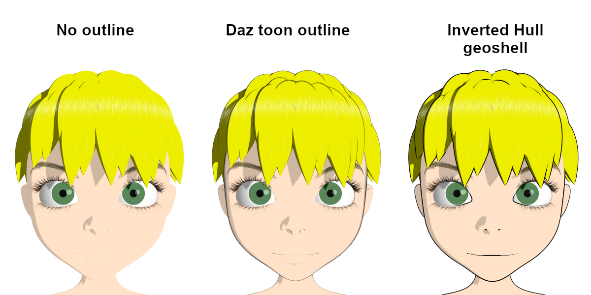
Ideally, I would just flip the normals on the geoshell and rely on automatic backface culling, like it can be done in other tools like Blender.
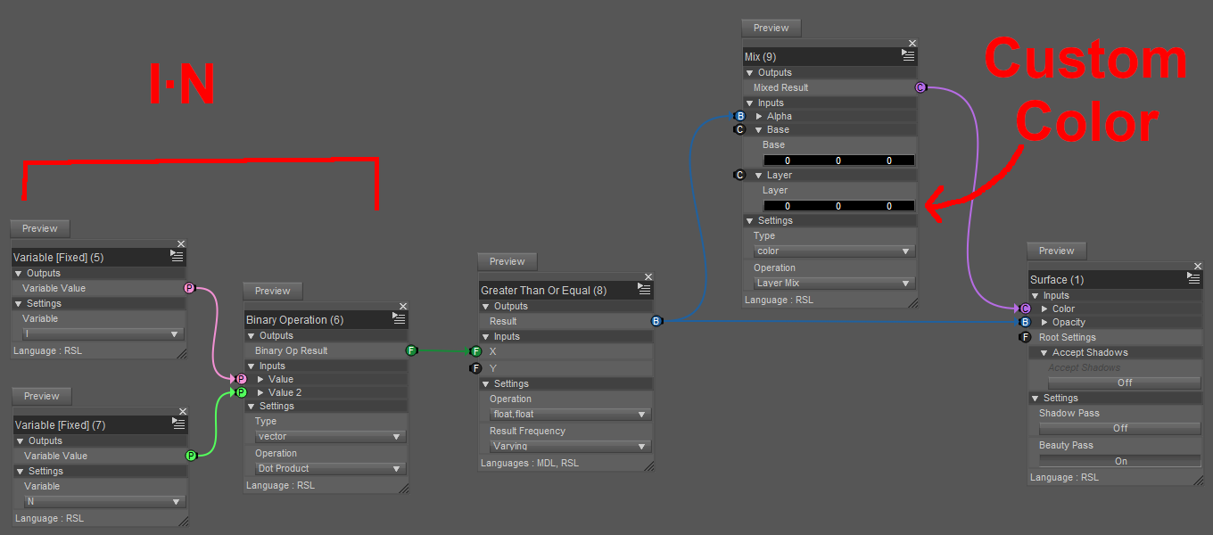
However, I couldn't find a simple way to do that in DS, so I decided to create a custom shader in which the dot product between the "I" vector variable and the normal is used to drive the opacity of the output.
The following picture shows the 3Delight shader used to generate the Inverted Hull effect above.
It works as expected in 3Delight, but can it be done in Iray?
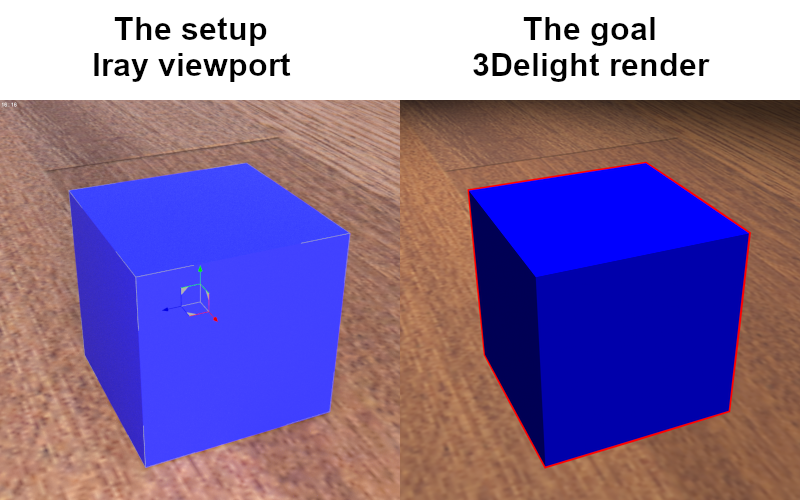
For the sake of clarity, I will be working with the following setup: textured plane + blue cube + red geoshell.
B) Inverted Hull in Iray
Initially, I couldn't find an equivalent to 3Delight's "I" vector variable, so I decided to manually input the position of the camera and subtract it from the pixel position to get the vector. It would have been inconvenient to manually copy the camera coordinates everytime, but if that is what it takes, so be it.
Thanks to a post on two-sided materials I was able to figure out a brick network that theoretically should have allowed me to do what I wanted:
1. Setup the foundation: User Parameters (Utility/User Parameters) → [Tint] Diffuse Reflection BSDF (MDL/Default Modules/df/Diffuse Reflection BSDF) → [Surface Scattering] Materials Fields (MDL/Materials/Material - Fields) → [Material] MDL Surface.
2. Compute the difference (Mathematical/Operators/Subtract) between the manually entered camera position input and the output of the Position brick (MDL/Default Modules/state/Position).
3. Normalize (Mathematical/Standard Functions/Normalize) and compute the dot product (Mathematical/Standard Functions/Dot) with the output of the Normal brick (MDL/Default Modules/state/Normal).
4. Compare to zero (Mathematical/Operators/Greater Than Or Equal) and connect to the [Geometry Cutout Opacity] pin of the Material Fields brick.
However, the results were disappointing and very frustrating, because the rendering looked somewhat random: some parts were visible, some parts were not visible, and tweaking the values would sometimes make the whole thing go dark, and I couldn't figure out what was going on.
Some web searching gave me several results seeming to suggest that backface culling in Iray might not be doable at all.
At this point, I had pretty much given up on the idea, but I still wanted to understand exactly why what I was doing was not working.
After hours of trying to connect the bricks in various ways and getting more and more confused, I noticed something surprising with this network:
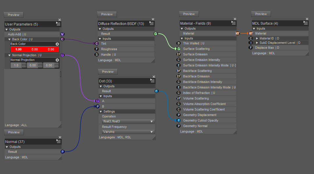
Here is what happens when orbiting around a cube with this shader (the cube is hidden, only the geoshell is shown):

It looks like a combination of frontface and backface culling. So there might be a way after all!
But based on my understanding of the shader, it shouldn't be doing that at all. More specifically, there is no information related to the camera that is being explicitly used in this shader, so the faces should be always invisible, or always visible.
So, how could they appear and disappear so consistently based on the viewpoint?
I don't have a lot of experience with Iray, so to me this was not obvious at all, but after thinking about it for a while, I came up with what sounds like a plausible explanation: each face has two opposite normals, and the Normal brick always returns the one that is facing the camera (same with the Geometry Normal brick).
In the shader above, the dot product selects all the normals that are facing the positive X direction, namely:
- the outside normals of the +X face of the cube;
- the inside normals of the -X face of the cube.
The inside normals of the +X face and the outside normals of the -X face all face backward (-X direction), which is why the faces disappear when the viewpoint moves behind the cube.
So now the question is: is there a way to determine which side (inside or outside) the camera is facing?
To find that out, I tried to think of ways that the orientation could affect the rendering. For example, would a positive displament become negative on the other side? Nope, displacements look the same on either side of a face.
What about textures, are the UVs changed on the other side? They aren't! So the texture coordinates contain information related to the orientation of the face.
Now, is there a way to get this information? A look at the list of bricks in (MDL/Default Modules/state) reveals bricks named Texture Tangent U and Texture Tangent V. If those are vectors in 3D space, then there is a way:
1. Compute the cross product W=UxV. W should be a vector normal to the surface but pointing only on the outside.
2. Compute the dot product W·N. The signum of this dot product should tell whether the normal that we are looking at is facing inside (<0) or outside (>0).
3. Set the geometry cutout opacity appropriately.
For testing purposes, I added a switch to toggle between frontface and backface culling. The shader looks more complicated than it actually is because I couldn't find a brick to compute a cross product, so I had to do it explicitly. Anyway, here it is:
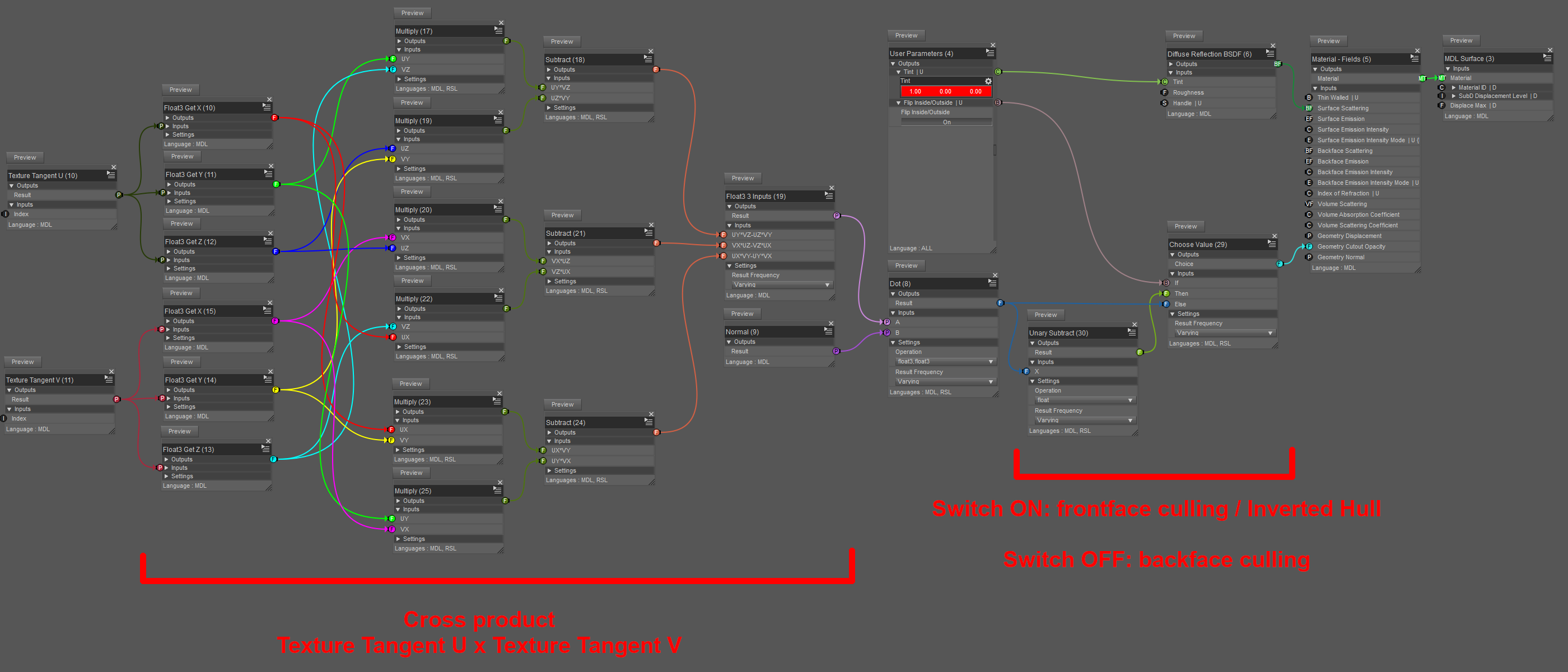
So I did all that, tested it, and... It works!
...
Sort of.
The good news is that this shader does backface culling with the switch ON. Here is a visualization after removing the top part of the box with an Iray section plane, so we can see that the geoshell faces are invisible from the inside (again, the cube is hidden, only the geoshell is shown):
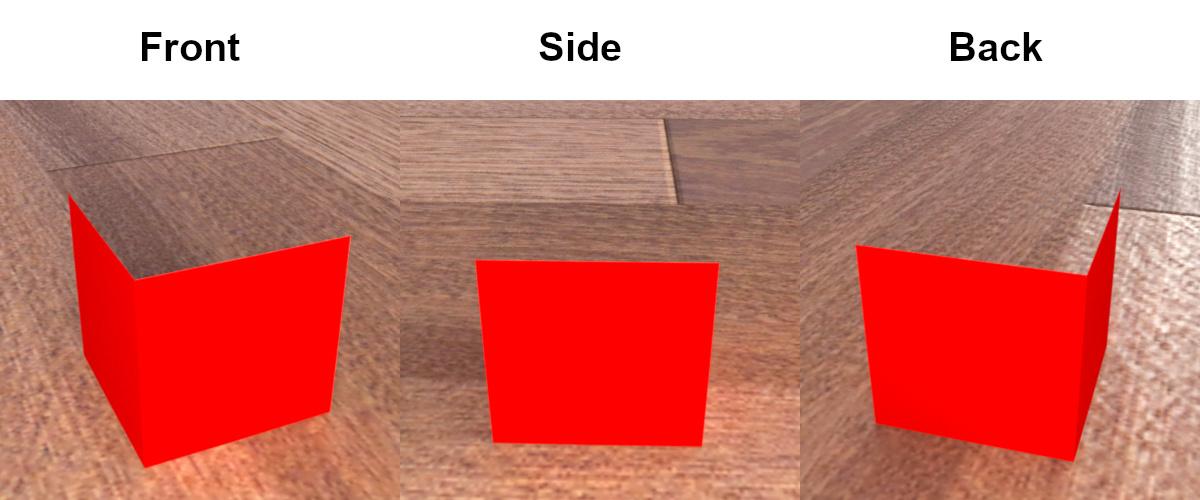
By the way, the shader can be applied to anything, it doesn't have to be a geoshell.
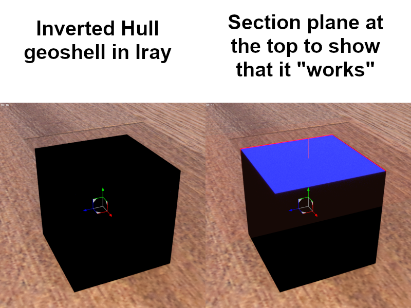
Now for the bad news. It seems that setting the cutout opacity dynamically in this way does not make the faces transparent to light rays.
In other words, even though we can see through them, as far as lighting is concerned, they are opaque. The following pictures show the results a couple of experiments, this time with the cube visible and the switch OFF.

I also tried using a different method, with a two-sided material setup with transparent glass on one side, but as soon as transparency is turned on, it all goes black. My guess is that you can have different materials on each side of a face, but if light is allowed to go through, it has to do it the same way on both sides. So if one side is opaque, then both are. (This is speculation only, as I don't know the actual details.)
C) Filament?
Filament has some kind of face culling, but I can't get it to work properly.
Flipping the normals on the model just makes the geoshell disappear.
And trying to write a shader doesn't work because it looks like Daz's implementation of Filament uses some fixed PBR pipeline internally, and all that matters is the label name of the input. For example, a color input labeled "Base Color" named "Diffuse Color" will allow to color the object even if it is not connected to anything in the shader.
D) Conclusions
It is possible to do backface culling in Iray.
However, light doesn't go through faces that are dynamically culled with geometry cutout opacity, so Inverted Hull doesn't work properly with the technique I presented.
Finally, using the Shader Mixer is... not an enjoyable experience. At all.


Comments
You might look at https://www.daz3d.com/double-sided-iray-fabric-shaders, making the "front" materials wholly invisible - of course you can't share the results, since it's a proprietary shader, but it might be a usable solution for your own purposes.
Thank you for your suggestion.
Unfortunately, I don't think it would work like you suggest because, for a closed* envelope with an opaque material on the inside and a wholly transparent material on the outside, the physically correct behavior is that light can't get in, and therefore there is only darkness inside, as observed on the outside through the transparent material. In other words, when Iray renders the object dark, it's probably what would actually happen if somehow we could build in this configuration a surface that is perfectly transparent on one side and perfectly opaque on the other.
*If you have an open piece of cloth, like a cape, you could see the objects behind as long as the lighting has a way to reach these objects by going around the cape.
That being said, I did manage to make some progress.
A) Backface culling in Iray with a double-sided shader
As I briefly explained at the end of section B in my previous post, I had already tried a custom-made double-sided shader without success. But based on my observations, I said "if one side is opaque, then both are." Now, I don't think it's completely wrong, but it is more complicated.
Consider for example this simple two-sided PBR shader (I only connected the pins that I needed for testing and transparency):
Applying this to a vertical plane with various parameter values we get:
What I get from these experiments is:
- The two refraction colors must be equal, otherwise the surface becomes black on both sides.
- The two refraction weights can be different, but only if neither is 0% or 100%, otherwise the surface becomes black on both sides.
Similar principles seem to apply to translucency weight and color.
B) Inverted Hull in Iray with a double-sided shader
A consequence of the above is that you can get a surface that is almost completely transparent on one side, and almost completely opaque on the other side. But if you want one side to be completely opaque or completely transparent, then the other one must be the same, otherwise they both become black.
What this means for the Inverted Hull is that you can't get the colors inside quite right, because increasing the opacity (to see the outline) reduces the amount of light that reaches the object. And conversely, reducing the opacity (to get more light on the object) reduces the visibility of the outline. So a even configuration that works well for backface culling when everything is well lit doesn't work so well to do an Inverted Hull.
Illustration:
It might be possible to get a decent compromise between the outline and the object by fiddling with the refraction weight of the inside material, but going further would require solving the fundamental problem, which is the same wether I use a double-sided shaders or a face culling shader: light can traverse from one side but not the other. Fortunately, there might be a way.
C) Inverted Hull in Iray with face culling v2
With this new understanding of the situation, we can come up with a way to do an Inverted Hull geoshell in Iray.
Remember in my previous post when I talked about the inside and outside of the +X and -X faces of the box?
When the viewpoint is in front (+X previously) of the box:
1. The outside of the +X faces must be transparent, so that we can see what is behind
2. The inside of the -X faces must be opaque, so that we can get the outline effect
3. (NEW) The inside of the +X faces must be transparent, so that light can enter (otherwise there is only darkness)
4. (NEW) The outside of the -X faces could probably be transparent (I am not entirely sure of the impact).
So there is only one case where the surface must be opaque (inside of the far faces), and everywhere else the surface must be transparent, so that we can see through and there is actually something to see.
The caveat here is that the shader must know where the viewpoint is, so we are back to having to enter the location manually.
The good news is that all those cases describe a classic backface culling, it's just using the oriented normal (W=UxV) instead of the output of the Normal brick.
So by modifying the face culling shader from my first post, I get:
A few notes:
- The brick at the bottom left corner is the result of the cross-product computation, same as before, see previous post.
- The values for the parameter "Viewpoint" are the coordinates of the camera.
And now the result:
There it is at last! A proper Inverted Hull in Iray! Granted, you have to manually input the viewpoint location whenever it changes, or perhaps just leave the camera in place and move everything else. But it works!
D) Conclusions
From my observations, double-sided materials can do almost complete opacity + transparency, but not complete opacity + transparency. It might however be enough for face culling and Inverted Hull if you are willing to accept some compromise in lighting quality.
Actual Inverted Hull is possible by modifying the classic face culling method and replacing I·N with (V-P)·W where:
- V is the manually entered viewpoint location;
- P is the output of the Position brick;
- W = U×V is the cross product between Texture Tangent U and Texture Tangent V; it is the oriented normal of the surface according to the UV information.
Neat, my son wants to anime so this could help him out.
I discovered a problem when trying to apply the method to some models, for example the Yamaki Rapture.
When I tried to render the Inverted Hull, many parts were rendered incorrectly, as if their normals were flipped, most noticeably the surface named body_mask_top which includes the whole top part of the bike from the back of the seat to the front above the wheel.
I thought that perhaps the UVs themselves were flipped, so I exported to Blender, flipped the UV islands corresponding to the top part of the mesh (scale -1 around X or Y axis), and imported the result into Daz as a new UV set (select object, then click Surfaces menu/Load UV Set, recreate geoshell (optional), choose new UV set in Inverted Hull shader).
This mostly fixed the problem, but not completely. Here is annotated picture of the Inverted Hull geoshell near the seat region above the back wheel:
After looking closely at the problematic parts in Blender, I saw this:
From what I understand, the way the UV quads twist on themselves makes it effectively impossible to get a consistent hull with the Tangent Texture UV method. I think that the overlapping is not a problem, but the twisting causes the Texture Tangent UV cross-product to flip. So, in order to get a good result, the UVs must be fixed.
So I regenerated the UVs in Blender (Select All, UV/Unwrap/Smart UV Project) and imported the result again as a new UV set in Daz.
It looks a lot better now:
However, if you look closely, you will notice that some parts still look wrong near the front and back wheels.
This happens because in those regions the mesh is not closed, it's just a surface that is covering what is behind. As a result, there is no back side, so no outline.
Unfortunately, fixing this would probably require actually modifying the mesh to add the missing faces, or modeling a separate closed object that could fit over the open part and which could use its own Inverted Hull geoshell to fill in the missing outlines.
is is remarkable how many DAZ models are full of flipped normals, most programs don't care but I use a few that load with backface culling by default and see it a lot.
Especially where one side was obviously duplicated.
I discovered a few more things, good and bad.
A) Cross product brick
I found a cross product brick! It's MDL/Default Modules/math/Cross.
So the ugly network from before can be simplified:
B) Emission
I was unable to get the emission pins on the MDL/Materials/Material - Fields brick to do anything, so I used MDL/Material Editors/Uber Add Emission to add emission to the shader:
The MDL/Default Module/df/Diffuse Reflection BSDF is connected to both the [Surface Scattering] and [Backface Scattering] pins of Material - Fields. Theoretically, I should only need the backface connection because that is the visible part of the Inverted Hull. However, if I don't connect things like this (or, alternatively, add a MDL/Material Editors/Copy Surface To Backface) then I can't get the colors to show properly, especially when emission is activated.
Also, [Thin Walled] and [Two Sided Light] are both needed to get the backface to emit without completely replacing the base color.
It looks complicated, because it is, but it is still simpler than the alternative without Uber Add Emission:
This alternative setup makes use of MDL/Materials/Material - Structs instead of Material - Fields. I didn't use MDL/Utility/Luminance Units this time because I don't know what Uber Add Emission does internally with the values.
The MDL/Default Module/df/Diffuse EDF brick is interesting here: unlike most of the other xDF bricks, it doesn't have any numeric* input. Instead, it is used to tell MDL/Built Ins/Types/Material Emission what kind of emission is going on (alternatives to Diffuse EDF like MDL/Default Modules/df/Spot EDF and MDL/Default Modules/df/Measured EDF do take arguments).
* The [Handle] pin allows to enter a string value. Rather than an input, it is an identifier for Light Path Expressions, as described in Iray - Programmer's Manual. I haven't tried yet, but I may have some use for it in the near future. More info:
- https://www.deviantart.com/linvanoak/journal/Iray-Light-Path-Expressions-in-DAZ-Studio-735776339
- https://www.daz3d.com/forums/discussion/205886/light-path-expressions-iray
C) More flipping issues
When working with multiple models, or when there are multiple shells, sometimes some geoshells turn black partially or completely, usually after a refresh following a parameter change. Sometimes it's limited to the Iray preview, but sometimes it also affects the render.
I don't quite understand why this happens, but there are a couple of workarounds:
- if the problem is only in the preview, then temporarily changing the geoshell offset and then reverting it back seems to do the trick.
- Sometimes it looks as if the UVs themselves get flipped internally for a set of specific surfaces (speculating here, as I really don't know what is going on). Example:
When that happens, preview and render are affected. Luckily, this one can be easily fixed by toggling the switch in the Inverted Hull shader for the affected surfaces. You can see how the switch is defined in the shader in my first post, although its meaning has changed now.
- Sometimes some parts that are dark in the preview are rendered properly, but when toggling the switch they are previewed correctly and rendered incorrectly. It's possible that the state of the switch gets lost up between the preview and the render, but I don't really know. Fortunately, restarting Daz Studio re-synchronizes the switches (or whatever is happening under the hood) so that they can be used again to fix the problem.
I haven't tested yet, but a potential drawback of this random flipping is that it might make animations impossible without checking each frame manually.
D) Going further
Inverted Hull geoshells are fairly simple, fast and powerful, but as these images show, they have clear limitations:
Inverted Hull only
Inverted Hull only
However, it is possible to fill in some of the missing lines with complementary edge detection techniques:
Inverted Hull + geometric edges
Inverted Hull + texture edges
In this last table, the cube and cylinder are outlined using both Inverted Hull geoshell (exterior outline) and geometric edge detection geoshell (inner lines).
I am trying to make the G8F 3Delight and Iray renders look similar, but I haven't succeeded yet. Be that as it may, both use the same method: The model (G8F Dev Load) is colored white and outlined with a black Inverted Hull geoshell, while the lips, pupils, irises and eyebrows are produced by a geoshell with a shader performing a simple edge detection on the default G8F face and eyes diffuse textures, and coloring them black (the color can be adjusted individually for each material name defined in the model).
I think that using shaders in this way to detect edges in textures is not a good idea for performance. Better to do the edge detection externally, and display the result on a dedicated geoshell. But if you are short on texture memory or want to test the effect of a LIE modification without leaving DS, then it might be of some use.
I will start a new thread for edge detection because it is a topic on its own. Update: link.