Edge detection and rendering in 3Delight and Iray
Update: the shaders in this thread were made with Daz Studio 4.15.0.30.
This is a follow-up to a post I made recently about generating an outline using the Inverted Hull method in 3Delight and Iray by applying a special shader to a geoshell.
This time, I will describe two methods that I use to detect edges using shaders in 3Delight and Iray:
- the geometric edges shaders detect sharp edges in the geometry by comparing the geometric normal with the smooth normal;
- the texture edges shaders performs standard image processing techniques (level filtering and convolutions, eg Sobel filtering) on a user-provided texture (not the screen).
In both cases, the result is rendered on a geoshell by controlling the opacity and color.
Of course, these methods come with a bunch of caveats, which I will summarize near the end.
Since this is going to be pretty long, I will make 2 posts, this one for geometric edges, and the next one for texture edges and conclusion.
Also, since I don't have an Nvidia GPU, everything that I present for Iray is CPU only, and it may not work at all for someone with a different hardware.
Part 1 of 2: Geometric edges
The following 3Delight renders show a combination of Inverted Hull and geometric edges (I replaced all the dragon materials with a white shader, except for the eyes):
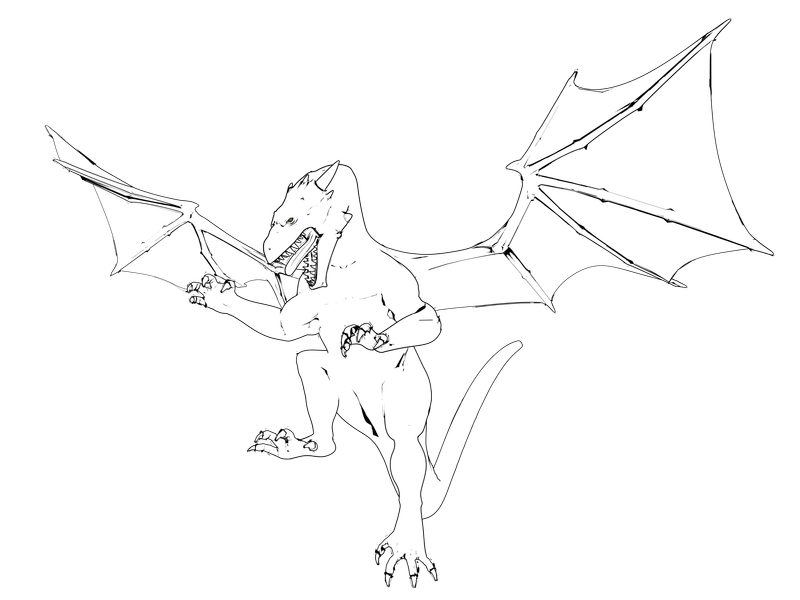
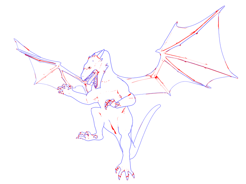
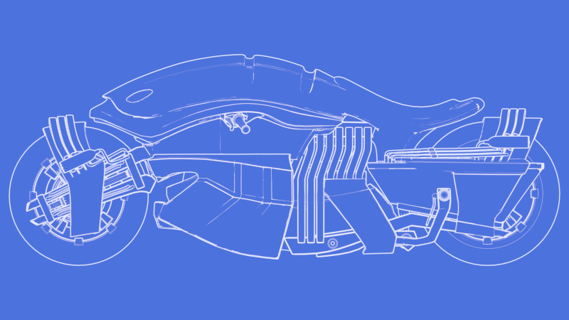
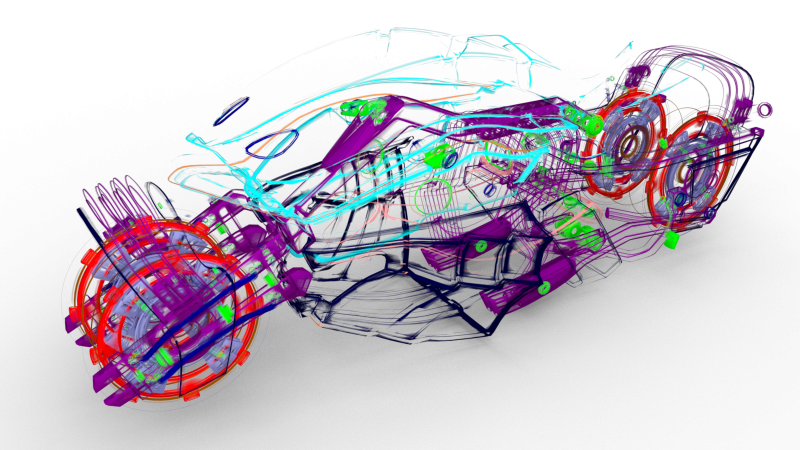
Although I am more interested in toon style, the shaders can be used for more technical styles, as the next 2 Iray renders illustrate:
A) Principle
The Inverted Hull method detects the geoshell edges when one side of the edge is facing toward the viewpoint, while the other is facing away from it. The sharpness of the edge isn't really important, only the viewing angle matters.
However, when doing Non-Photorealistic Rendering, common shapes have sharp edges that should be emphasized regardless of the viewing angle. The following picture illustrates my point:
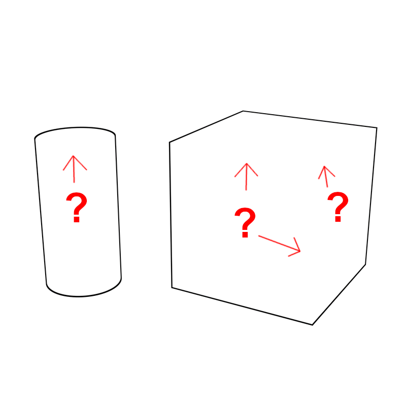
So, what can we do about it?
In Daz Studio, in the Surfaces pane, I noticed that each surface comes with "Smooth" and "Angle" parameters. They are used to control normal smoothing when previewing and rendering the surfaces. But, crucially, this smoothing only affects the normals but not the geometry itself. And both 3Delight and Iray allow access to the geometric normal (without smoothing) and the smooth normal in a shader.
Whenever this type of smoothing modifies the normal, the more smoothing there is, the more the normal is modified.
The smoothing is stronger near the edges and corners, and weaker to non-existent on flat surfaces.
Therefore, we can detect sharp edges and corners by:
- setting the smoothing parameters on the geoshell* surfaces so that edges and corners get smoothed (Smooth: On, Angle: 180°);
- measuring the distance between the smooth normal and the geometric normal as a proxy for sharpness.
* The smoothing on the geoshell and the object are independent, so changing the parameters won't affect the normals of the underlying object.
B) In 3Delight
The shader is fairly simple: get the geometric and smooth normals, normalize them (because some models have non-unit normals), compute the distance, threshold, color:
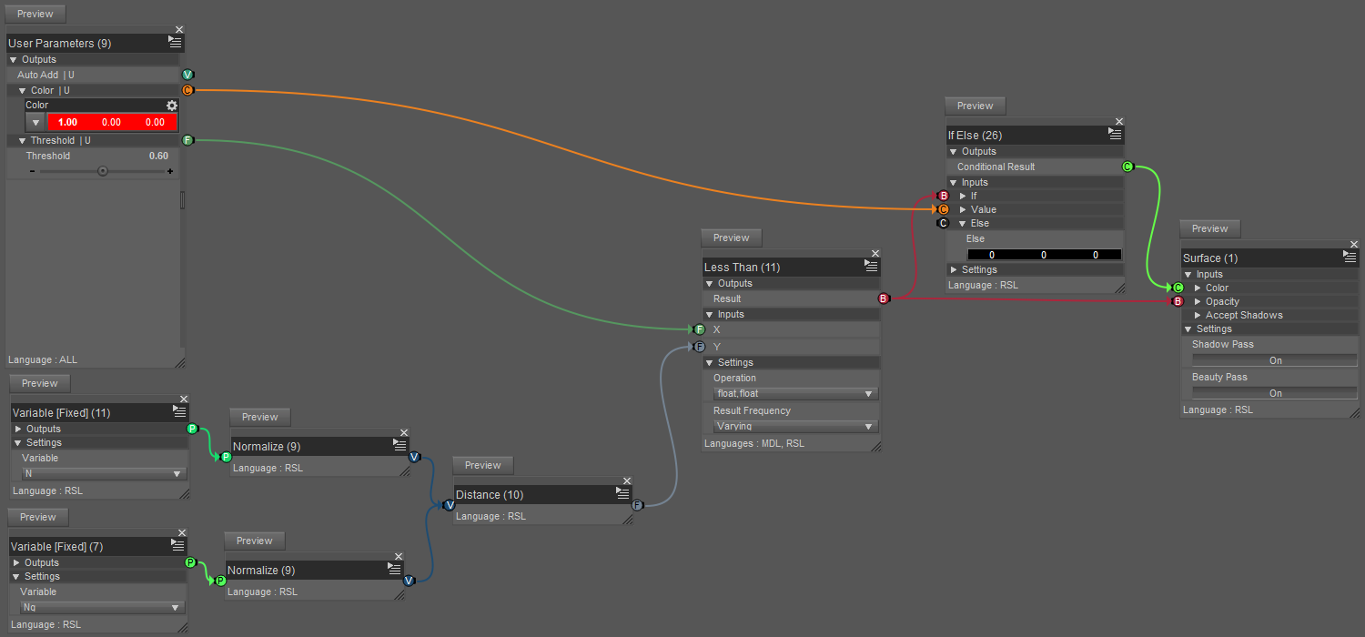
To test, create a cylinder and a cube, give them a white color, add a geoshell with this shader, and after fiddling with the parameters to get a result as good as possible, the result is this:
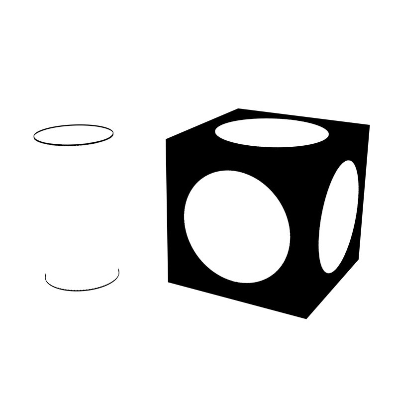
The cylinder looks pretty good, but what happened to the cube?
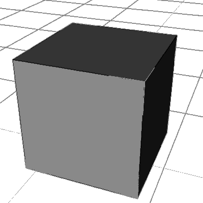
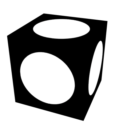
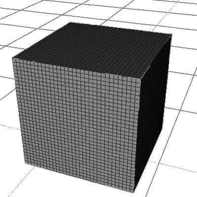
It turns out that the smoothing effect depends on the size of the mesh. So increasing the mesh resolution (Edit > Object > Geometry > Convert to SubD...) without changing its shape (SubDivision Algorithm: Bilinear) fixes the issue in this case:
| Mesh visualization | Geometric edges rendering |
|---|---|
 |
 |
 |
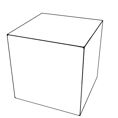 |
Notice that the cube's geometric edges give a complete outline of the object, but the same doesn't happen on the cylinder because of the curved side. By comparison, Inverted Hull almost* always gives an outline but may fail to detect inner surfaces depending on their orientation. So the two methods can complement each other.
* It doesn't work on open surfaces, like a simple plane. In fact, I don't yet have a technique that can put an outline around a plane (without post-processing or special texture).
C) In Iray
Iray is supposed to have a line/toon rendering feature (preview), but I don't know which brick to use, or if there is actually one.
Reproducing the 3Delight shader gives unexpected results (the normals on the cylinder have some kind of asymmetry) , but the situation can be improved by using the output of a Geometric/Bump Or Normal Map instead of a plain MDL/Default Modules/state/Normal. The results are then similar to what can be done in 3Delight, although still not exactly identical.
However, there is an alternative in Iray: MDL/Default Modules/state/Rounded Corner Normal.
Here is the shader:

Note that the Rounded Corner Normal has to be sent to the geometry normal output, otherwise it doesn't work.
The bricks named (G something) are groups that I created to keep things readable.
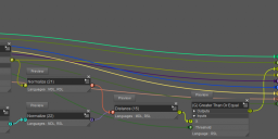
(G) Greater Than Or Equal only contains a Mathematical/Operators/Less Than connected to a Mathematical/Operators/Not. It is a workaround for what appears to be a bug on my machine whereby Greater Than behaves identically to Less Than.
The (G MDL) MT Diffuse Emission is a custom brick (created with Edit > Group Selected Bricks and then Save Custom Bricks from the brick's menu) that contains the lighting logic that I described in the thread on Inverted Hull. It is not necessary for the method, you can replace it with a PBR or an Uber brick if you prefer. But I will be reusing this group in part 2, and I thought it would be appropriate to describe it here. So, ungrouping my custom brick gives this:
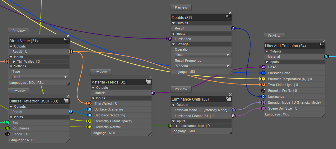
I used a MDL/Built Ins/Types/Double instead of a Utility/Direct Value for Luminance because I reuse this group in multiple shaders and I needed a one-dimensional (more convenient for me to connect to Utility/User Parameters) Varying input for the texture edges shader (next section) but Direct Value only works with Direct and Uniform (see this post for an explanation of Varying, Direct and Uniform). And I used a Direct Value for [Thin Walled] and [Two Sided] because they require a Uniform input.
Although the group bricks are tagged RSL, they are made of MDL bricks and they seem to work fine in Iray, but that may be because I am using CPU and not GPU.
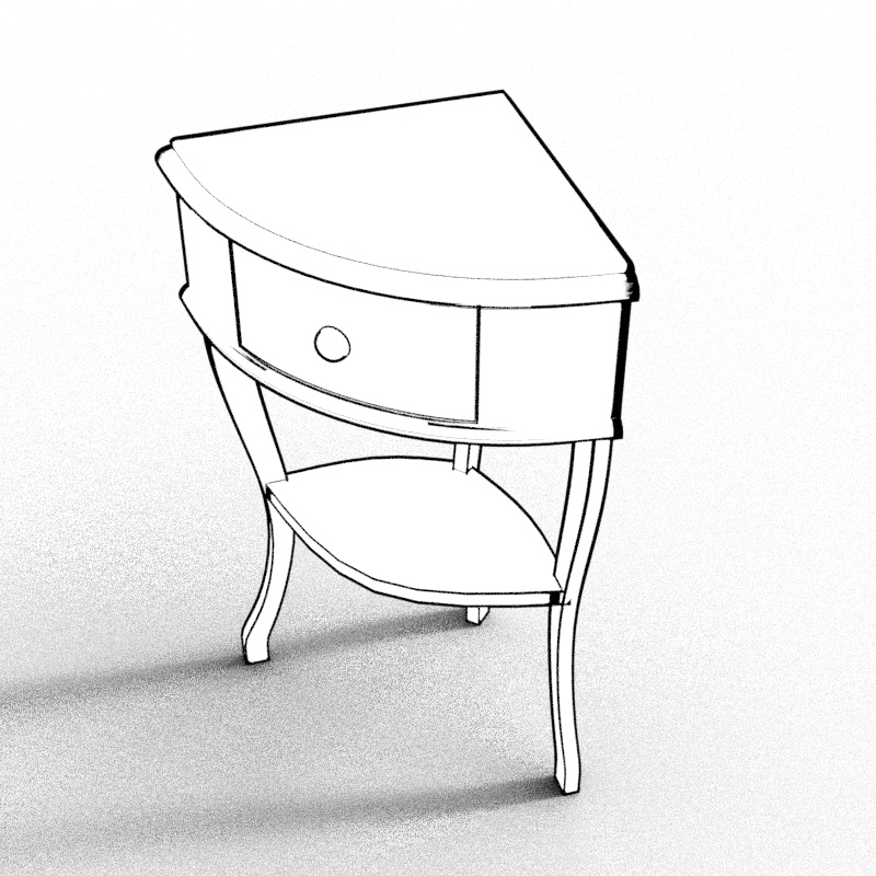
As for the result, here is a piece of furniture with Inverted Hull + geometric edges (model from European Style Apartment):
End of Part 1 of 2




Comments
SUPER THANKS for this !!
I dont have technical knowledges just pushing the pixels and doodling with surface parameters , so having someone who dig this "toon" solution alywas make me happy
Thanks again
Part 2 of 2: Texture edges
A) Principle
The idea is simply to build a shader that can perform standard image processing on static texture images. Although I reused some ideas that I learned from post-processing materials in Unreal Engine, this time the image has to be provided by the user, so this is not a screen post processing technique.
After experimenting a bit and thinking about what would be the most useful features for me, I settled on a pipeline comprised of a value filtering followed by and an edge detection with a Sobel-like operation. The filtering produces a region that can be visualized with a fill color, and the edge detection produces an outline that can be visualized with a stroke color. By "color" in Iray I mean diffuse + emission, so there is a full set of parameter for fill and another one for stroke (in 3Delight there is just one color fo now).
I will now give the details in plain words, and after that I will provide illustrations using the Iray version of the shader:
Step 1. Convert the image to single-channel data. This can be conveniently accomplished by combining Daz Studio's Image Editor (the "Grayscale From:" field) with the [Mono] output of the Textures/Texture Instance brick, which happens to be the same in RSL and MDL. So no need to create anything. Cool!
Step 2. Sample the texture at multiple texture locations grouped into what I call a patch. Since everything has to be hardcoded in the network structure, I chose to restrict my options to a 3x3 square patch (9 texture values). The sampling itself makes use of Textures/Texture Tiler and the user provided image dimensions to compute an offset of magnitude 1 pixel in texture space.
Step 3. Filter each of the 9 (single-channel) texture values with a band filter that keeps values inside Filter Min and Filter Max intact, and replaces everything else with Filter Min.
Step 4. Normalize the filtered value, so that the range [Filter Min, Filter Max] maps to [0, 1] (like Map Range in Blender). At this step, the center value of the patch can be thresholded to get the fill pixel detection F.
Step 5. Apply appropriate convolution kernels to the patch (I use Sobel X and Sobel Y, but they can be easily modified), combine and threshold them to get the boolean E indicating that an edge pixel has been detected.
Step 6. Combine the two detections to get the opacity (
Opacity = E Or F), and give priority to the edge detection when mixing the colors (Edge Weight = E,Fill Weight = F And (Not E)).B) The shaders
The shaders that I have presented so far have been relatively simple. This time though it's going to be a tad more challenging. It's not really difficult, but there is a lot of repetition so things get pretty bloated.
Luckily, the shaders in 3Delight and Iray look almost identical, so I will only illustrate using the Iray (MDL) version while mentioning the relevant differences.
I separated the screenshots into 3 parts:
- part 1 matches step 2 defined above;
- part 2 covers steps 3 to 5 and most of part 6;
- part 3 shows the end of part 6 (the mixing) and the final connections to the root brick.
B.1) User parameters and patch generation
The Utility/User Parameters is connected to a bunch of Utility/Direct Value bricks for the sake of clarity, but the connections could also be made directly.
Starting from the top we have:
- A Direct Value of type texture_2d that transmits the user-provided image to the patch generator (G) Texture Patch 3x3 (I will describe this custom brick shortly);
- 2 bricks that transmit the horizontal and vertical tiling information to the patch generator;
- A group of 9 bricks that collectively define the shape of the patch by nudging the horizontal and vertical tile offsets one pixel in each of the eight directions around the current texture pixel.
The (G) Texture Patch 3x3 brick is folded (brick menu > Hide Parameters) for the sake of clarity.
At this point, there is something very important to notice about the naming convention that I chose. I added a suffix to some of the output pins: [Horizontal Offset 0*], [Vertical Offset *0], [Horizontal Offset P*], and so on.
I use this system to help me connect the bricks that have many inputs and outputs, generally presented by Daz Studio in a semi-random order. "How many?" You ask. That many:
"Why?" you ask. I ask myself the same thing. Why Daz? Why is it that sometimes we can't create a group where an output pin connects to multiple bricks?
As a consequence of this very frustrating and somewhat unpredictable constraint, if you want to send a value (say, Horizontal Tiles) to multiple Texture Tiler in a group, well, apparently you can't. You have to have one input for each pin of each Texture Tiler.
Anyway, if you look at the pin names, you will see similar suffixes: 00, P0, 0N, NP, etc.
This naming works as follows:
- Given a direction, each character represent a relative offset for that direction: N=Negative, 0=Zero, P=Positive
- the first character is the offset relative to the current pixel in the +U (horizontal) direction;
- the second character is the offset relative to the current pixel in the +V (vertical) direction.
So, there are 9 groups of pins: NP, 0P, PP, N0, 00, NP, NN, 0N, PN.
It is absolutely essential that connected pins have a matching suffix. '*' matches with anything, but 'N' matches with 'N', '0' with '0', and 'P' with 'P'.
If there is no suffix, it means that all the pins should have the same value, and therefore be connected to the same pin (eg [Horizontal Tiles]).
"So, what's in the box?" You ask. This is what appears after ungrouping (G) Texture Patch 3x3:
I'm only showing the first two rows, but there are nine in total, one for each suffix. Notice that I connected bothe the MDL and RSL pins, so that the brick can be used in both 3Delight and Iray shaders.
Notice that only the [Mono **] pins are used. This is because step 1 is done using the Daz Studio Image Editor as I explained earlier, and the result of that step is retrieved using the [Mono] pin of Texture Instance.
B.2) Patch value filtering and edge detection
On the left, the two Direct Value bricks are simply transmitting the user parameters Filter Min and Filter Max.
B.2.1) Value filtering
The value filtering is accomplished with a custom (G MDL) Filter Patch 3x3 brick that simply performs the filtering on each of the nine inputs. The 3Delight shader has a (G RSL) Filter Patch 3x3 instead because of differences in some internal bricks, but both do the same thing. When unfolded, we see this:
This cutom brick was the worst to make because I couldn't include sub-groups. Or rather, I could include them, but then when saving the brick Daz would crash, and then when trying to restart it would crash again immediately, so I had to manually delete the saved brick, ungoup some of the contents, and create a humongous group. Here is what part of it looks like:
The MDL/Built Ins/Types/Double is there to create a float input pin and dispatch the value to mulitple bricks. I think this works because Daz forgot to add the code to make it crash.
The custom brick (G MDL) Between LELE Varying tests if (Min <= Value) And (Value <= Max). The naming is a bit weird because I have other variations of this in my custom bricks list.
The rest is a fairly straightforward linear Map Range (a very useful node in Blender).
B.2.2) Convolution
After filtering, the 9 values are sent to the convolution kernels. Here is (G) Convolution Kernel 3x3 Sobel X unfolded:
The inside is actually quite simple, and I could take advantage of the visual nature of Shader Mixer to make editing more convenient:
Notice how I arranged the inputs in a grid pattern in accordance to the suffixes. The (Group) WSum1 brick is simply a multiplication with a Direct Value, so that the value can be edited in place (instead of connecting to User Parameters). Notice also that the values match the Sobel coefficients.
The custom brick (G RSL) Sum 8 is mistitled, it should actually be "(G) Sum 8" because it is not RSL-specific. Anyway, the last two bricks simply add the outputs of the nine kernel bricks to complete the convolution operation.
B.2.3) Thresholding and mixing weights computation
Back to the picture at the beginning of subsection B.2, the convolutions in X and Y are combined into one value. Here I use the length of a 2D vector, but for 3Delight I had to do the computation explicitly.
The rest of the network follows the equations given in steps 4-6 in section A.
The custom brick (G) GE Varying is the Varying version of (G) Greater Than Or Equal that I discussed in Part 1. (G) GT Varying is the strict comparison variant.
B.3) Color mixing
Now that we have our two weights, we can finally mix the color parameters to display the pixel, or make it transparent depending on the Opacity value computed previously.
In the picture above, (G MDL) Diffuse Emission Param Mix mixes the user parameters according to the formula
P = Fill P * Fill Weight + Stroke P * Edge Weightwhere P is Tint, Roughness, Emission Color or Luminance.
(In the picture, Stroke Weight is the same as Edge Weight, I didn't notice the mismatch when I took the screenshot.)
In 3Delight there is only Fill Color and Stroke Color, so it is a bit simpler, but the formula is the same.
I already described (G MDL) MT Diffuse Emission in Part 1. Once again, it is not necessary to the method, you can replace it with your own lighting brick.
In 3Delight the mixed color goes directly to the Surface brick.
C) The results
With the textures G8FBaseFaceMapD_1001.jpg and G8FBaseEyes01_1007.jpg, I tried to extract details of the lips, eyebrows and irises by placing the texture edges shader defined above in a texture edges geoshell where only the Lips, Face and Irises surfaces are activated.
I was running a bit short on time so I couldn't really explore all the possibilities, but I think it should be possible to do find better parameters for these elements.
The lips especially didn't turn out well with these parameters, so I changed the color to black, opened the mouth slightly to get some Inverted Hull, and added a smudge of geometric edges. Still doesn't look very good, but I think there is potential.
Here is the Iray render:
For the 3Delight render, I ran into an issue with the geometric edges: sometimes the Ng brick returns a smooth normal, thereby breaking the edge detection. I don't really understand when or why it happens, but a workaround is to duplicate the model and put the geometric edges geoshell on the invisible duplicate at base resolution, while the texture edges and Inverted Hull are on the visible high-resolution mesh. This is what I did for the dragon at the beginning of this thread, and this is what it looks like on G8F in 3Delight:
All the object surfaces are white except for the pupils and the elastic bands on the sports bra which are black.
The G8F has 3 geoshells: Texture Edges, Geometric Edges (on a separate invisible base resolution mesh), Inverted Hull.
The sports bra has 2 geoshells: Geometric Edges (on a separate invisible base resolution mesh), Inverted Hull.
A few comments:
- The face is missing lines, but without shading I'm not sure that I can improve that.
- Speaking of the face, it is a delicate and complex mesh, so putting important features on a geoshell at an offset above 1 mm can result in distorted features. Unfortunately I can't have the geoshells too close to the model or some features might disappear altogether.
- In general, the geometric edges tend to generate "smudges"; unfortunately I don't yet have a way to remove the smudges without losing the edges than I want.
- The model could probably use some eyelashes. And hair in general, but my hair technique is still not quite there yet.
D) Conclusions for part 1 and part 2
The bottom line is that it is possible to do line art directly with 3Delight and Iray shaders without post-processing.
However, it is not guaranteed that a given model will be compatible with the methods that I have presented:
- The UV faces must be oriented consistently within each material in order to use the Inverted Hull in Iray.
- The faces sharing a sharp edge must be relatively small in order to get a good geometric edge rendering in 3Delight; subdivision can be used for this purpose. Note however that the Rounded Corner Normal brick in Iray seems to avoid this issue under some circumstances. (Edited to add that RC edges detection can require subdiv.)
- High resolution smooth meshes reduce the difference between smooth and geometric normals, so the edge detection is negatively impacted. That was the case for the dragon at the beginning of part 1.
- Edge beveling created during modeling doesn't look so good with geometric edges applied: either each line of the bevel is rendered, or nothing at all is rendered because the geometry itself is just too smooth (partial case in the funiture render at th end of part 1).
- None of the techniques that I have tried work on flat open surfaces like a simple plane. So if you have a model that contains disconnected planes (like Study Desk02 in Library Study Room) then nothing that I have shown will work on these parts.
There are still a couple of line techniques that I want to try out, but I will be adding shading soon.
End of Part 2 of 2
Great timing! I am preparing to make a bunch of coloring pages for children (hopefully from scenes I have already made in the past). I have been trying other methods. I will experiment with this and possibly mix and match other stuff I have been trying (ie. I own the Visual Style Shaders - I took the script and tweaked it to produce a wider range of color effects and in one rendering method just having different high contrast colors next to each other will render a line io-between ... I will explain in more detail if they mix well).
You're welcome. If you found any of this helpful, then my goal has been achieved.
I am still experimenting with a bunch of NPR stuff right now, and I will try to post more soon.
Sounds cool, please let me know how it turns out.
My experiments have been about toon style effects without post-processing. But, as you have seen, the models have to fit a number of criteria to apply my shaders: good UV layout, small polygons around sharp edges, no modeled bevels, no disconnected flat surfaces.
If you want a more flexible option for your line art, you might want to consider post-processing using Scripted 3Delight Outline (choose render engine Scripted 3Delight, and in the Render Script section choose Outline). I only discovered this recently so I don't know what the limits are, but it looked pretty decent when I tried it.
I added 2 features to the geometric edges shader:
- Fresnel edges, based on the classic Fresnel outline effect;
- bump edges, a simple form of texture processing that allows to extract edges from height maps and normal maps.
A) Fresnel edges
People who make cel shaders sometimes include some kind of Fresnel-like effect to produce an outline.
This is probably what the RSL brick Geometric/Special/Toon Outline does internally.
Although it has some characteristic visual flaws, this effect is generally decent and, as I will illustrate later, is a good complement to the "smooth edges" detection of the geometric edges shader (I call "RC edges" the special case of smooth edges obtained with the rounded corner brick in Iray).
A1) In 3Delight
Recreating this effect to get a better control over the thickness is relatively easy with 3Delight. Compute the dot product I.N (same as in Inverted Hull), take the absolute value and threshold below (instead of above) to get an opaque band facing the sides of the model (relative to the viewpoint). Here I modify the geometric edges shader to add the customizable Fresnel effect (bottom half of the picture):
This is what it looks like on a geoshell around 3 simple shapes, a sphere, a cylinder, and a cube:
The sphere is fully outlined, only the rounded parts (sides) of the cylinder are outlined, and the cube is invisible because it is white on a white background and Fresnel edges don't work well on large flat surfaces.
Adding the smooth edges we get:
I had to increase the subdiv level of the cube to get the smooth edges, but I also had to increase the subdiv level of the cylinder to prevent a distortion of the Fresnel edges resulting from the >90° normal smoothing required for the smooth edge detection.
All these adjustments are inconvenient to make, but the end result is that a single geoshell with a geometric edges shader combining smooth edges and Fresnel edges can reproduce the appearance that has so far required an Inverted Hull geoshell in addition to the geometric edges with smooth edges only.
But there is a but:
This weird ugly effect is characteristic of Fresnel edges. It is particularly visible on limbs (which are more or less cylindrical) and props with flat surfaces.
The cube doesn't actually need the Fresnel edges, so it can simply be turned off, but for the cylinder, we can try to decrease the Fresnel and risk losing the sides, or turn it off completely and add an Inverted Hull.
I don't know if there is a better way to deal with this.
A2) In Iray
I found several MDL bricks that relate to Fresnel, but most of them didn't give me the effect that I wanted, until I found MDL/Material Editors/Layering/Add Custom Curve Layer.
Here is a brick setup to use it:
Notice that the parameter values require changing or deactivating the limits.
Here is what it looks like directly on a sphere, cylinder and cube (no geoshell yet):
This is the typical look of the Fresnel edge effect, and despite its flaw, it would be useful to include in a cel shader.
However, I am presently concerned only with line work, and unfortunately there doesn't appear to be a way to get the computed Fresnel value from the material bricks. I need this value to drive the opacity, or alternatively I need a way to make the inner part transparent.
So I tried replacing the inner material with a MDL/Materials/Simple/Thin Glass:
And, to my surprise, it worked!
Same objects untouched but viewed from the left:
But wait, can I actually use this as a geoshell or is it going to turn black like before (see backface culling thread)?
Well...
That works too! And DS hasn't even crashed yet. How lucky!
The geoshells in this last render are oversized on purpose, otherwise the picture would look identical to the one earlier without geoshell.
So, there is obvious potential here, but first I need to find a way to better control the cutoff angle, because looking at the cube and cylinder, it can't be used on flat surfaces as it is.
B) Bump Edges
The texture edges shader is powerful but quite big, often unnecessarily complicated (not really my fault, DS often crashes when trying various simplifications) and quite slow on my machine (the image processing that takes so long to render is near instantaneous in an image manipulation software).
But there is actually a simpler and faster method to detect edges in texture images: bump map. By bump map I mean either height map or normal map, but it is not entirely clear to me what the correct terminology is in Daz Studio.
For Iray, the brick Geometric/Bump Or Normal Map can take as input either a height map or a normal map, and outputs a "Mapped Normal."
Since the output is a normal, we can normalize it and compute the distance to the smooth normal to get a smooth edge detector operating on the input image. This can be convenient to quickly get edges from an existing normal map.
Given the algorithmic similarity with smooth edge detection, I decided to include it in the geometric edges shader, like the Fresnel edges.
Partial view of the brick setup in Iray:

The 3Delight version with a Geometric/Special/Texture Instance Displacement brick that only takes a height map as input:
Like the texture edges shader, it is probably better to do the processing externally and use the result directly as a texture. Nevertheless, I find it convenient to have an edge extraction that works in near real-time directly on top of the 3D model, although the uses are more limited than the other edge detection methods.
Here is the result of bump edge extraction in Iray on the normal map from https://3dtextures.me/2019/09/11/jungle-floor-001/:
C) Examples rendered in 3Delight
Example 1
Comments
The eyes (orbits) are white instead of black because there is no lighting or shading of any kind, just white models with black lines. I will start working on shading soon.
Credits
The moon is a simple white sphere with a geometry edges geoshell that performs height map edge extraction on a height map of the moon.
Credit for the moon height map: NASA's Scientific Visualization Studio
The skeleton is the M4 Skeleton from the Anatomy Starter Bundle.
The sword is the Dark Fantasy Long Blade from Dark Fantasy Weapons for Genesis 3 and 8 Female(s). It is originally made of disconnected open surfaces, so I had to edit it in Blender to merge the overlapping vertices before being able to use it with my shaders (Inverted Hull and geometric edges [smooth edges]).
The skeleton pose is Dual Wielding 024 from Dual Wielding for Gianni 6 and Genesis 2 male(s).
Example 2
Comments
G8F is wearing a mask for health reasons, it's totally not because her lips look ugly.
There are several places where the Inverted Hulls from multiple parts interfere and cancel out. I can add a Fresnel edge to prevent a blank, but I can't increase the width of the Fresnel edge without introducing Fresnel artifacts elsewhere (look at the left index finger).
I was able to get the line on the bridge of the nose with a Fresnel edge. However, it created an artifact at the top of the head where the face and torso surfaces meet, so I increased the thickness of the Fresnel edge on the torso to match.
The moon is the same as before, but viewed from a slightly different angle.
Credits
The mask is a selection of helmet parts from Andromeda Sci-Fi Outfit for Genesis 8 Female(s).
The gun is from Sketchfab. It's the model 9 mm by Slava Zemlyanik, licensed under Creative Commons Attribution. I edited it in Blender to isolate the gun, simplify the mesh (Delete > Limited Dissolve) and convert the triangles to quads (Face > Tris to Quads). In Daz I added a white material and two geoshells (Inverted Hull and geometric edges).
The pose I made myself, which explains why it looks wonky.
C) Conclusions
The set of line detection shaders that I made is mostly working. There are still annoying quirks here and there, and parameter adjustments have to be made for each model in order to get a decent result.
It is unfortunate that some models have to be edited, but hoping for a one-click solution would probably have been too optimistic.
Finally, I actually implemented in Iray a Fresnel effect similar to the one I showed for 3Delight. It uses a shader parameter for the viewpoint, like the Inverted Hull shader, but is otherwise similar to the 3Delight version. Because of the inconvenience of the viewpoint parameter, I see this more as a backup option in case I can't get the "proper" material-based Fresnel option working like I need. I will post an update when I have news.
Fresnel edges in Iray
A) The proper way that almost works
A1) Basic version
I was able to get a better control on the thickness of the Fresnel edge. Unfortunately, I didn't succeed in getting the effect to work properly with emission. For some reason, the Fresnel effect simply discards all emissive effects in the layer. And if I append an MDL/Material Editors/Uber Add Emission, the whole surface becomes emissive, including the fully transparent part.
It is frustrating that Iray can manage surfaces where one half is fully opaque and the other half is fully transparent, and even somehow surfaces that are both fully transparent and emissive, but I couldn't get a non-emissive transparent half and an emissive other half. I even tried a new shader with a simple split material setup combined with MDL/Material Editors/Normalized Surface Mix, but the emissive effect never appears.
Anyway, since I couldn't get the effect that I wanted, I decided to put what I had in a new shader, and perhaps come back to it later:
I connected the emission pins, but they don't do anything.
The custom brick (G MDL) MT Transparent is mostly a
MDL/Materials/Simple/Thin Glasswith default values that I need to achieve the full transparency effect:The main part of the Fresnel edges shader, (G MDL) MT Fresnel Transition Uniform Size is made of two custom bricks:
I will start with the second one, (G MDL) MT Fresnel Transition, because it is simpler and also more important:
Like (G MDL) Transparent, it's only a wrapper for MDL/Material Editors/Layering/Add Custom Curve Layer with default values that give the Fresnel edge effect. I set it up so that the thickness of the effect is entirely controlled by the Curve Exponent parameter.
Notice that I let this parameter in its Varying state while everything else is now Uniform. This is because I needed this parameter to be varying in order to integrate the effect with the rest of the geometric edges shader (for testing), but everything else could just keep the defaults.
Which brings me to (G) Fresnel Size To Curve Exponent Uniform. It looks a bit scary, but there is a reason for all this:
The whole point of this sub-network is to make the Fresnel effect easier to control by the user with a slider that goes from 0 (Fresnel effect barely visible) to 1 (the whole surface is covered with the layer material and the transparency is gone).
This is useful because the raw curve exponent:
- varies the wrong way (increasing the exponent makes the edge vanish);
- is uncomfortably non-linear (when the effect is large, small changes in the exponent cause sudden wide visual changes, and when the effect is small, changing the exponent only has a small effect).
So, to solve these two issues:
- I decided to limit the user-accessible Fresnel Size parameter between 0 and 1;
- this value is then inverted using a custom (G) Complement Uniform brick, which is essentially a subtraction (1-X);
- I flatten the low values with a power function with an exponent > 1 (in this case it's 2 > 1);
- I multiply the result with a moderately large factor (100) to get more visual thinning.
These last two step are similar to a gamma expansion, if that helps.
Interesting thing: Internally, the (G) Complement Uniform uses a custom (G) 1 brick, really a mere Utility/Direct Value that I retitled and saved, which is tagged both RSL and MDL, and it is the only brick that actually appears in the Custom Bricks section of my brickyard with MDL language filter. Mysteriously, all my other custom bricks are tagged RSL only (even those that should be MDL only), and are only accessible with RSL language filter, or no language filter.
So, if all of this doesn't do emission, then what does it do?
I put it on a geoshell and to test it on the gun prop because it has lots of interesting shapes (flats, curves, bumps, holes) without being overpowering like the Yamaki Rapture:
In the first picture (Fresnel Size = 0), the edges of the gun are barely visible. They are not completely off because of how the curve exponent works (see explanation above). I should probably change the defaults to make the edges disappear completely.
In the second picture (Fresnel Size = 0.5), we start seeing more edges. This is the usual appearance of a NPR Fresnel effect on a an object with many flat surfaces and sharp angles.
Note that the black and gray area are not shadows or related to lighting in any way, as there is no lighting in this scene (it's all white emission from the model and black regions on the geoshell). Instead, they are artifacts of the Fresnel method, like I showed in my previous post. I don't know for sure why some of the affected areas are gray. Perhaps it is because of the stochastic nature of Iray in an unstable (grazing) Fresnel region: some rays go through and produce white, others don't and produce black, and the aggegation is some shade of gray. Or it could be due to the mixing itself, as done by Add Custom Curve Layer, because the transition is not sharp enough.
I have seen many renders like this, and I guess people like this look. Personally, I am not a fan, and I would rather avoid it if possible.
In the third picture (Fresnel Size = 0.7), we can see even more details of the gun's geometry, but now the Fresnel artifact are becoming overpowering, resulting in a visual mess.
Personal taste notwithstanding, this is an important and useful effect, and this shader works without a viewpoint parameter, unlike the one I will present in section B.
A2) Pointiness-modulated version
It is possible to improve the previous results by turning off the Fresnel edges on flat surfaces.
This can be accomplished with a texture image encoding the curvature of the surface.
For example, in Blender, the following node setup can be baked using Cycles to generate a pointiness map:
Quick steps: import the object, assign a new material to the surfaces, make sure that Cycles is selected in the render properties, edit the material to look like the above (the node on the right is an image texture with a new empty 4k texture), go tothe render properties and hit Bake, review the image in the Rendering workspace, and save it as BW PNG (for example).
I was hoping that Iray would have a similar feature, but I wasn't able to find it. The closest that I can think of right now is the RC edges detector that I described in a previous post, but it is not an exact replacement, especially when it comes to cylindrical sides.
Back to Daz, we can visualize this map on the model, and do a quick threshold to reveal the edges:
Adding it as a modulator to the Fresnel edges shader we get:
I already described the custom bricks. What is new here is the MDL/Default Modules/math/Lerp which computes a linear interpolation, but since the input is boolean, it behaves like an if-then-else. Notice that the output of the Lerp is Varying, which is necessary because the data arriving to the pin [L] is Varying.
Funny thing regarding the Lerp pins: before I discovered this brick, I was already familiar with Mathematical/Mix in RSL which takes 3 inputs: Alpha, Base, Layer. In that order. The first time I saw Lerp, I thought "A, B, L? Oh yeah, I get it!" But then of course it didn't work at all because, actually, A = Base, B = Layer and L = Alpha. SMH.
And now, the result:
This was rendered with Fresnel Size 0.78 and a pointiness threshold of 0.24.
Notice that there are more details than the raw Fresnel Size 0.5 render, and significantly less artifacts than the horrid Fresnel Size 0.7.
Notice also that the cylinder at the tip was all white in the pointiness threshold image, whereas here it is replaced with proper (albeit thick) Fresnel edges. This shows that you can't just replace the Fresnel edges with the pointiness data, you need both to get a better effect.
However, this method has two important drawbacks:
- here I had to generate the map in 4k to reduce aliasing artifacts, and even then it's still noticeable;
- it only works for rigid objects or parts.
Luckily, the first issue can be dealt with (I will likely post about it in the future), and the second one isn't a problem for props, or even characters that don't deform too much, like skeletons.
B) The inconvenient way
I need both emission and diffuse working properly for my cel shading experiments (future thread) so I decided to update the geometric shader by adding a modulated fresnel with parametric viewpoint, the same trick I use in Inverted Hull.
This is the relevant portion of the shader:
Starting on the left, there is a custom brick (G MDL) Unit View Vector which is used to process the user-provided Viewpoint parameter, just like what I did in the Inverted Hull shader, with some improvements like the possibility to switch between perspective and orthographic camera. Here is what it looks like ungrouped:
If you focus on the Utility/Choose Value brick, the label should help understand what is going on: if the camera is orthographic, just use the provided viewpoint as view vector, otherwise compute the view vector by taking into account the 3D position of the pixel.
Back to the previous picture. After normalization, I compute the dot product between the Unit View Vector and a smooth normal, for example RC Normal (Rounded Corner). Using the RC normal will make it possible for the Fresnel effect to apply to edges of flat surfaces like a cube faces. Unlike the Inverted Hull, I don't need the oriented normal because I just want a band around the region where the smooth normal transitions between facing away/toward the viewpoint. So I can just give this dot product to a Mathematical/Standard Functions/Abs to make it symmetric around 0 and get a non-negative value which I can then threshold with the user input labeled "Fresnel Edges | Threshold."
The binary value that we have at this point is the Fresnel edge opacity. It's what causes the Fresnel effect if we plug it directly into the opacity output.
However, based on the previous experiment, I wanted to add some modulation. The geometric edges shader already had a texture-based edge detector using bump (height or normal) maps. So I decided to use it with the pointiness map, and I added a user-controlled threshold parameter for the computed bump value to be used specifically for Fresnel edge modulation. The bump map thresholding is performed by the brick titled "Less Than Or Equal (38)." The output, labeled "Fresnel Edges | Bump Opacity" is then used to modulate "Fresnel Edges | Opacity" via a Mathematical/Operators/Logical AND brick.
While I was there, I thought I might as well add a modulation using the RC edges, in order to get more edges by increasing the Fresnel threshold and modulating it with either the bump edges or the RC edges, or both.
So the 3 Logical AND bricks generate a bi-modulated Fresnel edge detection, labeled "Fresnel Edges | Modulated Opacity."
This in turn gets connected to the rest of the shader with simple logical Or operations:
I didn't show the whole shader, as I have already described the rest in previous posts, but that's it.
Now time for the Iray render:
There is only one geoshell with the geometric edges shader, no Inverted Hull.
I used the parameters RC Edges 0.75, Bump Edges 0.005, Fresnel* 0.80, Fresnel Bump 0.001, Fresnel RC 0.30.
* The Fresnel threshold here is not exactly equivalent to the Fresnel Size in the previous section, but the two behave similarly.
Despite having a pretty high Fresnel threshold, the picture doesn't look dark thanks to the bi-modulation, and we get a lot of lines.
It has a kind of pencil sketch feel to it, probably due to the combined effects of the pixellation of the pointiness map and the edge detection performed by the bump brick. It's an interesting effect to keep it in mind, but it is not what I intended, as I was aiming for clean and crisp lines. So I will have to fix that eventually.
C) Conclusions
Post-processing line detectors classically use normal and depth information to automatically extract edges.
But with what I have done so far, I have to carefully select which shaders and shader features to use depending on the type of geometry of every single object and surface. It's definitely more complicated, but it is quite satisfying to have an interactive stylized 3D model in the Iray preview. And while my Iray renders are a bit slow (because I don't have an Nvidia GPU), it has so far been possible to do fast iterations with 3Delight by getting the final result directly in the render window in seconds, or a few minutes at most.
There are still improvements that I have in mind for the modulated Fresnel. For instance, it might be possible to ditch the pointiness map by fiddling with the RC parameters, but I am not certain yet. And having to use a 4k map for this quality of result is not ideal, so I will have to fix that.
For now though, I will focus more on cel shading, and start a new thread soon.