How do I add uniform windows to this model in Hex without using boolean?
 Ademnus
Posts: 744
Ademnus
Posts: 744
I included my starship body model below. I want to add many windows of uniform size. The finished model needs to export as an .obj so boolean won't cut it, pun intended. ;p How on earth do I do this?
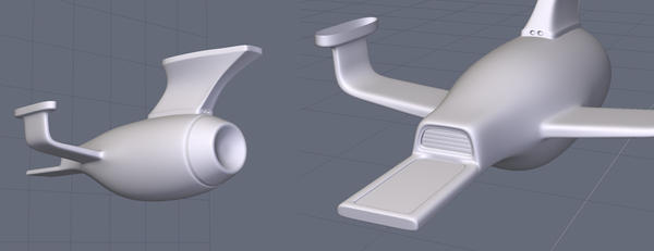
as1.jpg
800 x 308 - 82K
Daz 3D is part of 
Connect
DAZ Productions, Inc.
7533 S Center View Ct #4664
West Jordan, UT 84084
Licensing Agreement | Terms of Service | Privacy Policy | EULA
© 2024 Daz Productions Inc. All Rights Reserved.
Comments
If the ship is a subdivision surface, here is an old video by Brad Peebler of Luxology and Pixar's Rich Hurrey in which he demonstrates the general approach to cutting holes into hulls.
Hurrey uses modo, but he demonstrates agnostic technique...as long as your modeler can move vertices around in 3D space, it should be applicable.
http://community.thefoundry.co.uk/tv/training/view.aspx?id=207
Edit: It's a combination interview/demonstration so you'll have to skip around in the video a bit to find the segment. iirc, it's toward the end.
....aaaand, edit #2: The more I look at this and consider the number and scale of the windows you're likely to want to cut, the more I wonder if maybe you'd be better off exporting the smooth hull and then tricking the viewports up with displacement and luminosity maps.
Will not help in this instance, but in the future, you'll want to model those windows early on so that they are already there before you start smoothing the model.
unsmooth everything, select individual faces (split them up if you have to) and then do an extrude inward. Then resmooth. you'll have your widow areas. from there you can loop edges to get a window profile line around the window, and turn those into flat surfaces to become the window.
alternatively, you could just use texturing and bump maps to make up the windows.
Ach that's a problem. The poly's are not uniform enough to have identical shaped windows throughout if I do the first method. Based on UV and the curve of the surface, if I use the second method some will be warped.
In Lightwave you can "stencil" by placing shapes against one another and it will create a poly on the object of the face that's touching it. You can make 100 identical window shaped tubes, jam them into the ship and hit "stencil." Then you can grab the window shaped polys and extrude and so forth.
Hexagon has nothing like that?
well if the poly's aren't uniform enough for that, then even if you were to 'stencil' windows onto it, that would still mess with the smoothness of the surrounding geometry/normals. hexagon doesn't really have anything that comprehensive.
like, if you were to even use something like zbrush or sculptris, you'd still end up with issues due to the non uniform poly's.
anything you'd try to do regarding windows would probably be very tedious and would be difficult to get just right. that's why I suggest adding windows with textures and bump maps. heck of a lot easier. since you'll probably be using tons of tiny windows, this would be the most efficient way. it doesn't need to be actual geometry.
I agree with what previous posters write - modelling takes some planning.
If you don't have an unsmoothed copy of the model - you should always keep one - then your best bet at this stage is to fake it with a transmap.
Here is a little trick - based on the fact that a perfectly square hole will smooth into a perfectly round hole.
Select the verts where you want the holes, select chamfer under the surface modelling tab, set the range to 0 and slowly increase the radius. You will see diamond shapes forming around the verts. When they are the right size, validate, delete the diamond shapes and smooth level 2. This will work with unevenly spaced polys because the diamond shapes are centered on the verts.
I wouldn't recommend this for a cylindrical shape, because it is pretty much impossible to prevent puckering - the holes will be raised above the rest of the surface.
I don't quite understand the process you describe using Lightwave; it seems to be a variation of Boolean. I'd be interested to know why you feel that Boolean is not an option when exporting as .obj. Fully agree that Boolean is not always the best option, but it is certainly a last resort option, done correctly and provided you fix the resulting n-gons.
Here's what happens when you export a boolean cut .obj and draw it into a renderer, like DS. On the left, you see hexagon with a nice sphere boolean cut into a cube. On the right, it is an .obj in DS. Note the hole is covered by a distorted polygon-like shape that is twisted and stretching off to one corner? Boolean is really great but only if you are staying in the native format of the modeler.
As I wrote - you need to clean up the mesh after doing a Boolean operation. What you are getting there is DS not knowing how to read n-gons - other more sophisticated applications can deal with it, but not DS, or, I believe, Poser.
Try opening that in Hexagon, and, with the object selected go to Utilities -> Triangulate n-gons. This will work in DS, but if it results in a lot of long, thin tri's converging on a corner, it could give rendering artifacts.
Triangulating n-gons isn't the best way to clean up the mess, but it gives you a starting point from which to do a proper cleanup and end up with all quads.
simple tiny windows like that - best done with either normal mapping or bump mapping. you can do boolean and triangulate ngons, but the edges would still be sharp for the windows and would probably mess with the smoothing of the rest of the model.
this is basically what you're shooting for geometry wise.
this only looks good on a flat surface though. you start cutting boolean out of more than one face, while the faces are also curved, and you'll end up with a lot of visual issues.
@user.operator - I don't think you use DS, do you?
Those tri's converging on the corners cause render artifacts. DS is not very sophisticated with mesh handling. What I meant about cleaning up after doing a Boolean operation is more like the attached pic - all quads :)
I totally agree that at this point in the OP's model, there are easier, more effective ways than Boolean to get the results wanted.
Quick example of how it could have been done with some planning - no Boolean:)
With planning + booleans.
:) :) :)
Goes to show that there are many ways to skin a cat!
The common denominator is planning :)
Yes, this is me asking for tips on how to plan this because making the model that shape took some hoop-jumping and poly's fall where they may. I have no idea how to exactingly create the shapes I want to, so often I end up with a mesh that tells me what to do instead of the other way around. How can I create the mesh in such a way as to have the capability for square, with rounded edges, windows inset evenly and uniformly?
you're simply not going to be able to do what you want without either
1) tediously redoing the whole model with preplanning and design to add that many windows
which will
a) make your model way too resource taxing than it needs to be
and
b) probably won't look exactly right anyways and will require even more tedious work to make minor changes
OR
2) Bump mapping
go with the bump mapping.
they're tiny windows, they don't need to be geometry.
I you are asking how to go about planning a model, in general, not fixing what you already have?
There are probably as many methods as there are modelers and you will have to settle on your own method. I can only give pointers to my personal method.
I'd start off with a sketch, reference images, blueprints, whatever. Need to have the final model firmly fixed in my mind before starting. I study that until I'm very sure of what it is I want to do. Then decide on what method, or combination of methods to use. How much detail will be modeled and how much will be be done through bump maps, etc. How will it be textured, will it be animated?
Then I plan backwards to the start - break it up into the component basic shapes and start rough, then refine and add detail, all the time keeping in mind how each will be UV mapped and textured. I keep it in as many separate meshes as what I can get away with. This makes it easier to make corrections, or even start again if I mess up, as well as making UV mapping easier.
Always keep an unsmoothed copy, for just in case. Apart from saving regularly, I also export as .obj regularly, in case the .hxn file gets corrupted, I can recover it through the .obj, which is universal and can be recovered through any of the many applications I use.
Regularly run through the "diagnostic tools" at the bottom end of the "Selection" tab, as well as checking for flipped normals. These are pretty much unique to Hex and can save you a lot of problems down the line by early identification of any issues.
Lastly, it is usually faster to trash and start again than to try to fix a mess - all it costs is time.
Thing is, I know all of that. I'm talking about the specifics of planning windows into this mesh, not the generalities of planning ahead.
the problem is the difficulty rises exponentially with rounded models, especially ones that have tons of non uniform faces of varying sizes.
the absolute easiest way other than bump mapping, is to export it to a different program like sculptris, and use the brushes to create window shaped indentations as desired.
i would really not suggest manually creating windows though, it would be a highly inefficient use of time and would severely up rendering times for very little difference in visual quality...it may even reduce visual quality, not to mention make UV mapping many times more tedious. in the end you'll probably end up with an unworkable model if you try to add physical window.
here is a section of a curved surface with geometry windows, but notice how there are imperfections. this also wouldn't work so well with non uniform sized faces to extrude. And this little section alone is over 7,500 faces.
boolean is just really out of the question if you want a nice clean model, but you could copy certain sections from the model, then copy on support with some spheres, and then do one big massive boolean at once.....but I doubt it would be pretty, especially once you triangulate the resulting ngons.
As I see it,you have three options;-
1. Start from scratch and plan it to have the windows;
2. Delete the parts of the hull that need to have windows, remodel with the windows and weld that into the model;
3. UV map it and paint the windows and bump - or normal map - in Photoshop or similar. Photoshop has a plugin for normal maps, as does Gimp. With Gimp you can get a free plugin "Insane Bump", which is every bit as good as Crazy Bump.