Spring is here and so are n-gons
 Roman_K2
Posts: 1,252
Roman_K2
Posts: 1,252
First time using the Close tool, to patch the hole in the end of the crossbar in the letter "T" in my typography project.
I'm probably not doing something right because the tool isn't working as per the tutorial, and I'm getting n-gons (the red arrow).
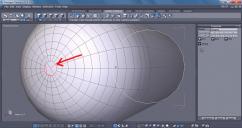
close-tool-not-working.jpg
1024 x 542 - 162K
Daz 3D is part of 
Connect
DAZ Productions, Inc.
7533 S Center View Ct #4664
West Jordan, UT 84084
Licensing Agreement | Terms of Service | Privacy Policy | EULA
© 2025 Daz Productions Inc. All Rights Reserved.
Comments
Ok, I tried it again and the dome closed off properly. Ha, they laughed when I started to model using Hexagon!
I finished the first version of my letterform and it wasn't too bad although some shaders seem to... do funny things when they encounter a weld or a tweak, in my mesh - or a properly done, very smooth ring (like in the center of the letterform). Also I noticed a tendency on my part, to make the outline a bit on the thin side relative to the reference image... that's ok, I have yet to figure out the snap to function.
My next version of this model is going to be smoother!
Btw having the final render come out looking like a plastic balloon was a big surprise.
It does not look like all the sections are joined, to check, select one of the lines which goes all the way around the S (bottom left to top right) and select loop. If you have done it correctly the line will run all the way, if it stops then you have 2 or more pieces (I see 3 parts).
If it is wrong, select a face where it is not joined, loop it and delete them. So now you should see you have two seperate objects, loop both ends and use the bridge tool to join them. Repeat the other parts and do the above check again.
Thanks, I'm definitely having problems with seams and joints and welds, and I don't yet know the "Bridge" function. Off to Youtube and the Reference manual to look it up.
Here's the letter "T" which is much simpler, consisting of just two straight pieces. The swirly thing on the bottom is just something I was trying, and I do know what caused the black marks in this 2-hour render.
If this was a physical model I would want to use some glue or body putty where the two pieces join together; if the software was PhotoShop then I'm circle the joint with the fuzzy lasso and I'd give it some Gaussian or Motion blur!
1. Ok I'm getting better at making a smooth form. I'm sure there are other (and better) ways of doing this, but for now what the hey, eh.
2. I turned a tubular section around and attempted to "loop" the two facing open ends, to see what the join would be like. Clicking "Bridge" gave me a red circle where the loop on the right was, then I had to painstakingly click, click, click on the loop elements on the left-side object. As I'm doing this I'm thinking there must be a better way... okay so the two objects were sort of "joined" as one but with an open space. Sending the combined sections to DS 4.8 yielded what you see in this screenshot, eg. there's air space between the sections!
Maybe "weld" is better? Also I think I will be able to experiment better and faster if I just try joining two open-ended cubes, right?
Got a new screen recorder the other day so I thought I'd give it a try (got it from GOTD).
Please note I use short-cut keys etc so keep an eye on the command viewer (top right of working window).
http://youtu.be/g6F2w8AiZi8
Edit. When I'm drawing the lines I'm holding down the Shift key to snap the new ones onto the curves.
Tried to reply yesterday but it wouldn't take my post! Screen recorder looked good but - no sound! Still, I know enough now (a little knowledge can be a dangerous thing, heh) that I was able to get through well past the first half while understanding 90-95 percent of the functions and what's being done... when you started cutting the "O" ring though there were a couple of things I didn't understand.
I *think* I understand, though, that you are saying that it's easy to slice through the object, to begin to make a letter "C" or a "J" out of the O shape, and also the relatively low number of segments means that there's a minimal work-load involved in bending the whole thing into a "S".
Took me a while... yes, I think I get it now. General screenshot is from your video.
Ok, is "snap to" just for drawing these lines... reason I ask is I had a sense that it was a quick way of positioning any two objects (or possibly vertices) together. When I was making my wheel -- separate thread -- I was thinking that I could set the "top" or lid of the wheel down on the map object using the "snap to" function...
About the snap lines thing, not really sure, this is the way I've always done it so I have not tried the snap align route with lines. I draw line 1, then with line 2 I select the option to start the next one from the choices given in the properties tab and use the shift key to snap it to line 3 (the other half circle in the above example). Then weld them all when finished.
By the way, when drawing lines try tapping the space bar, it will go from free hand (at an angle) to straight up/down and straight left/right.
What I was trying to show is the fact that sometimes it looks like you have one object, to check this is the case you use the loop command to highlight a line or a series of faces.
Snap Align tool, I learnt from Gary Miller - here is one he did which explained it to me -
http://www.geekatplay.com/hp1.php
But, I think it is worth working your way through all 4 series of video he has done (also the ones by Danny (CG Dreams)).
(May 16, 2016) Still having trouble remembering functions like the circle and the sweep tool, and "Snap..." seems to elude me (time to go back to the documentation) but the second video put me over the top as to how you "thicken" a polyline so that it looks more like a pencil or a noodle. Really helped me able to get my letter "S" project done and opened up all sorts of other possibilities.
I chose random colors for the object - green and yellow for this first attempt. Good enough for now, thanks.
The only other comment I have is that it still feels REALLY WEIRD drawing a polyline, in Hexagon. It's dooable, just creepy... for me anyway.
Heh heh... making the letter "i" look like cast metal was a lot easier, heh.
Here is one way to explain how you can handle a cylinder with a spherical dome end.
For making S or other curved shapes, does hexagon have the ability to work with bezier or nurb curves that can then be converted to mesh? I work in Blender, but many 3D programs have similar things.
Edit: Thicken polyline sounds like it should work.
Concerning joining two cylinders for a T, hope this is useful.
Wow, that looks really good where you've smoothed the join at the "T" shape. Thanks!
Yes, IIRC most people seem to work with a polyline, to get the "S" and similar curved shapes in Hexagon, and they either thicken the polyline or "sweep" it into a desired shape in terms of what the cross section is going to be, eg. round, elipse or rectangular.
Ok re: the different way to round off a cylinder... I seem to be comfortable with multiple extrusions, in Hexagon and the "Close" function seems to work well -- it hiccupped the first time I tried it -- but I'm not up on my Buckminster Fuller-physics; not nearly knowledgeable enough at this end, to recognize a better way to close off a mesh.
I noticed this passage just now in the reference guide: "...brushes can be used on triangles, quadrangles or n-sided polygons (also called “n-gons”). Choose however if possible quadrangles, in order to get better quality results. To conclude, try to keep in mind the following three important rules:
Try to have polygons as square as possible.
Try to have a mesh with a density as uniform as possible.
Try to have as many quadrangles as possible..." [emphasis added here by me]
So this would sort of corroborate, maybe, your suggestion about switching to quads. If you were going in the direction, so to speak, that fewer polys at the apex of the curve was neater and thus somehow easier to close off, then my hats off to ya... I'm just not there yet.
Btw if you can do that thing like you did with the "T" thirty more times (26 letters of the alphabet, plus some punctuation) then that equals a saleable model in the DAZ store! Think "puffy"... to my knowledge nobody has ever done a sky-writing font! That stuff on Google is pretty lame IMO... http://www.infoparrot.com/sky-writing-effect-in-photoshop/
As to extruding and closing, you can extrude and on the final loop, merge to center. You will then get what I have in my illustration and just remove every other edge to make the quads instead of the triangle fan.
Ok, I just now looked up "Merge". This the one? http://docs.daz3d.com/doku.php/public/software/hexagon/2/referenceguide/utilities/start#merge_duplicated_points
I wonder if this merge function -- or something similar -- would help with, say, the cracks in this old model of my letter "S", seen in a grainy Iray render from several weeks ago. The way I would describe the problem with that... model is that there are at least 3 pairs of loops which aren't exactly the right size and they're not lined up perfectly... this was due to my lack of skill at that time. <smile>
I used merge on the cap ends to merge the row of points into one. Some programs call it welding. Not sure for Hexagon. Between sections, I connected with bridging. I believe Hexagon has bridging.
Ok, working on it... Hexagon definitely has briding features but "connect" -- which sounds similar -- is apparently used to put in more crossbars like when you change a quadrangle into two triangles but drawing a line through the center, from the top left corner say to the bottom right.
Poking about with various other terms in Hexagon I encountered a scary-sounding: decimate. Turns out that this is also a thing which reduces the geometry a bit, "while preserving the global aspect" of the object. Learn something new every day, heh.
http://docs.daz3d.com/doku.php/public/software/hexagon/2/referenceguide/utilities/start#decimate
I'm not sure if this applies, but a small tip for the end of your first image is to select faces/lines, and use the Vertex Modeling > Average Weld feature, it will give you a properties panel that says 'Distance' and you can slide the value up or down for the desired effect. It can range from collapsing ngons to doing something similar to decimate by reducing complexity.
Sounds like something to try - thanks. I'm still not up on the Weld and Target Weld stuff and so on.
Here's something I tried. I made the upper half of a letter C, and then copied and rotated it to become the bottom half. Then I welded the two "halves" together. Sending it to DS made it easier to look at - view "A" below, and when I rotated it a bit - views "B" and "C" it was clear that it was a bit crooked, but somewhere along the line when I grouped or welded (or smoothed) the two halves I lost access to the raw mesh for further editing.
Idea!
Sending it back to Hexagon makes it a kind of raw mesh all over again, and I was able to straighten it out a bit... I wonder if this is a good sort of work-flow then? I previously had not thought of "Hex to DS and then back again to Hex".